
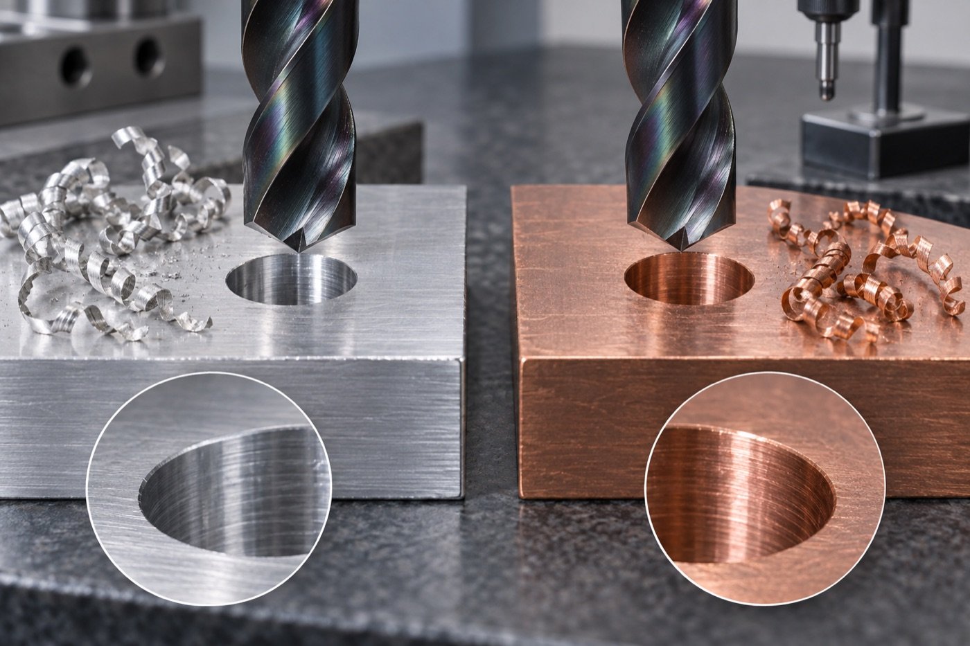
Aluminum and copper do not normally demand the hardest coating; they demand a sharp, low-friction cutting system that limits adhesion and moves chips out of the hole. DLC can be useful, but coating choice must be matched to alloy, geometry, coolant, machine stability and hole depth rather than treated as a universal upgrade.
Why non-ferrous drilling fails differently
Many aluminum and copper failures begin with material adhering to the cutting edge. Built-up edge changes the effective geometry, raises cutting load, damages the hole surface and can block the flute. A coating may reduce adhesion, but a blunt edge, restricted flute or poor coolant path can cancel that benefit.
| Symptom | Likely mechanism | First buyer check |
|---|---|---|
| Material welded to the lip | Adhesion, heat or insufficient lubrication | Edge finish, coolant and actual cutting speed |
| Long tangled chips | Geometry does not control the alloy | Chip-breaker form and feed per revolution |
| Oversize or rough hole | Built-up edge, runout or chip recutting | Toolholder runout and chip evacuation |
| Sudden head damage | Chip packing, interrupted cut or unstable setup | Hole depth, exit condition and body rigidity |
What DLC contributes
Diamond-like carbon coatings are used for their low-friction behaviour and resistance to material adhesion in suitable non-ferrous applications. The exact coating architecture and permissible temperature window matter. Buyers should request the coating designation, intended alloy range and a test recommendation rather than accept “black coating” or “DLC-like” appearance as proof.
Geometry remains the primary control
A sharp edge, polished surface, appropriate rake, lip symmetry and enough flute area usually determine whether chips leave cleanly. For deep holes, confirm how the head breaks chips and how coolant reaches the tip. A coating cannot compensate for a drill body that is too flexible or a margin that rubs.
Exchangeable head or solid carbide?
| Factor | Exchangeable head | Solid carbide drill |
|---|---|---|
| Carbide consumption | Only the cutting head is replaced | Whole tool contains carbide |
| Diameter repeatability | Depends on head/body interface and head consistency | Depends on grinding and regrinding control |
| Inventory | Bodies plus replaceable heads | Complete tools by diameter and length |
| Very small or special geometry | May be limited by system range | Often more design freedom |
Do not copy published cutting data blindly
Manufacturer test data is a starting point, not a transferable guarantee. Alloy temper, silicon content, copper grade, machine spindle, holder, coolant concentration and hole depth can materially change the safe window. Begin within the supplier’s stated range and qualify the tool on your own part.
Incoming verification
- Confirm head grade, coating and lot identification.
- Check the interface for damage, contamination and full seating.
- Measure assembled runout using the supplier’s method.
- Compare edge condition and coating coverage under magnification.
- Retain the first approved head and hole report as the repeat-order reference.
Trial plan and cost per hole
Compare the current drill and candidate on the same alloy lot, machine, holder, coolant and hole depth. Record acceptable holes, cycle time, diameter, roundness if relevant, burr, surface condition, chip form, unplanned stops and head-change time. Include the reusable body, lost production and rejected parts in cost per acceptable hole.