
Composite decking can look like timber, but its cutting behavior depends on the actual board construction. A wood-plastic composite (WPC), a cellular PVC board and a capped composite board can respond differently to the same blade. That is why a buyer should not approve a blade from the words “for composite decking” alone.
The practical approach is to identify the board, define the cut and qualify the complete saw–blade–board setup. This guide explains what to record, how to diagnose poor edges and how to run a useful sample trial before a wholesale order.
Scope: This is a buyer’s selection and trial guide. Follow the decking and saw manufacturers’ current instructions. Brand-specific blade advice is evidence for that brand’s material system, not a universal tooth-count rule.
Start with the board, not the blade
Ask the board supplier for the product name, thickness, width, core construction and surface layer. Keep a labeled sample from the same production range that will be used in the trial.
| Board description | What it may contain | Why it matters for cutting |
|---|---|---|
| Uncapped WPC | Polymer, wood flour or fibers, mineral fillers and pigments | Heat, filler content and chip formation can change the edge response |
| Capped composite | Composite core with a protective polymer cap | A clean core cut can still be rejected if the cap chips or lifts |
| Cellular or foamed PVC | Polymer structure without the same wood-fiber core as WPC | Heat can smear the edge; support and chip clearance remain important |
| Coextruded or multilayer board | Different core and surface materials | One layer may chip while another softens or tears |
Do not infer the composition from color or wood-grain texture. “Composite,” “WPC” and “PVC” are commercial categories, not a complete cutting specification.
For broader material matching, see Wryno’s saw blade guide for wood, plastics and composites.
Define the cut before selecting the saw blade
Crosscutting to length and ripping along a board create different loads. A short crosscut may favor surface finish, while a long rip needs adequate chip space and stable guidance. Notches and curves may require a jigsaw or another process instead of forcing one circular blade to do every operation.
Record these points:
- crosscut, rip, miter, notch or trim;
- handheld circular saw, miter saw, table saw or another machine;
- blade diameter, bore, maximum permitted speed and rotation direction;
- board position, visible face and required edge;
- board support, fence or guide arrangement;
- extraction, ambient temperature and whether the board was hot from direct sunlight;
- production goal: occasional installation cuts, repeated jobsite cuts or factory processing.
Trex and TimberTech both publish procedures for cutting their own decking systems. Their guidance shows why support, a sharp carbide blade, accurate marking and controlled feed matter. Their product-specific tooth-count or tool recommendations should stay attached to the named board and saw size.
Before ordering, also confirm diameter, arbor, kerf and RPM compatibility. A suitable cutting geometry cannot correct a blade that does not fit the machine.
Translate “clean cut” into an acceptance standard
“No chipping” is too vague for a supplier trial. Agree which face and which portion of the edge will be inspected, then use photographs and a simple rating scale.
| Result to inspect | Acceptable example | Rejection example | Record during the trial |
|---|---|---|---|
| Protective cap | Continuous edge with no objectionable lifting | Chips, cracks, lifted cap or white stress marks | Face orientation, cut direction and defect length |
| Core edge | Stable, reasonably uniform surface | Torn core, deep void breakout or loose material | Board batch, blade and feed method |
| Heat effect | No visible smear that affects fit or appearance | Glossy melted ridge, fused debris or discolored edge | Board temperature, blade condition and pauses |
| Straightness | Cut remains within the agreed line or dimensional tolerance | Wandering, bevel error or an out-of-square end | Guide method, support and measured deviation |
| Burr or feathering | Removable minor feathering if allowed | Heavy burr that interferes with installation | Which face is critical and whether deburring is permitted |
Photograph the full cut and representative close-ups. A single attractive section can hide chipping at entry or exit.
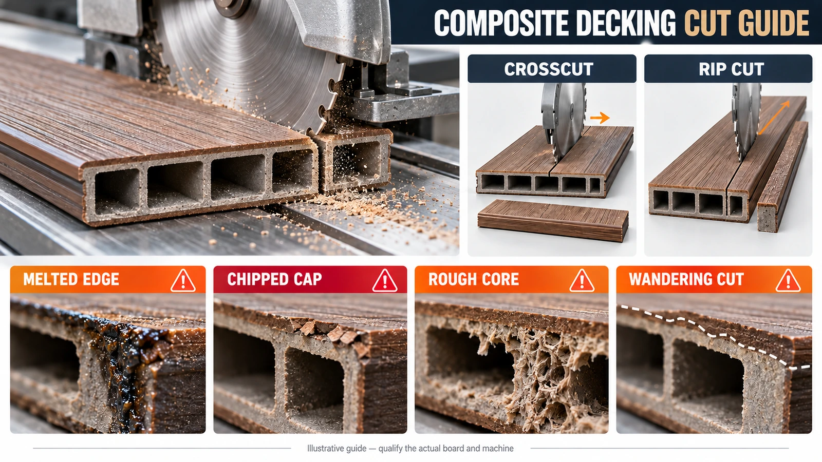
Diagnose melted, chipped, rough or wandering edges
Change one factor at a time. Otherwise, a better result will not tell you which correction worked.
| Symptom | Check first | Then check | Avoid this shortcut |
|---|---|---|---|
| Melted or smeared edge | Blade sharpness, debris buildup and feed interruptions | Tooth geometry, chip clearance, board temperature and extraction | Assuming a higher tooth count always lowers heat |
| Chipped cap | Visible-face orientation and entry/exit direction | Support near the cut, vibration, blade condition and feed stability | Increasing feed force to finish faster |
| Rough or torn core | Blade damage and chip evacuation | Board composition, support and tooth form | Judging only the top face |
| Cut wanders | Guide, fence, baseplate and board movement | Blade stiffness, projection, runout and operator correction | Using side pressure to steer a binding blade |
| Burning or heavy dust | Resin/debris buildup and rubbing | Incorrect blade, slow intermittent feed, damaged saw or extraction | Continuing until the blade is visibly overheated |
More teeth often improve finish in a stable crosscut, but tooth count works together with diameter, tooth geometry, gullet volume, kerf, blade plate, speed and feed. The tooth-count buyer guide explains those relationships in more detail.
Run a controlled sample-cut trial
- Freeze the inputs. Label the board batch, blade sample, saw, guide and operator. Record board temperature and storage condition.
- Inspect the setup. Confirm blade fit, rotation, guards, base or fence condition, support and extraction. Follow the equipment manuals.
- Make repeat cuts. Include the required crosscut and rip operations. Use enough cuts to see whether the result remains stable after the first clean edge.
- Record time and interruptions. Measure cutting time or length, but also note stops, binding, chip packing and cleaning.
- Rate the edge. Use the agreed photos, measurements and visible-face requirements.
- Inspect the blade. Look for buildup, damage and uneven wear. Do not infer long service life from a short trial.
- Repeat after one controlled change. If the edge fails, change only one variable before retesting.
Trex’s guide emphasizes complete board support and a controlled cut. TimberTech distinguishes crosscuts from rip cuts and recommends a guide for circular-saw ripping. Those are useful setup principles, but final approval still needs the buyer’s actual board.
Compare cost per accepted cut
A low blade price can be offset by rejected boards, slow setup, cleaning and frequent blade changes. For a repeat application, record:
- purchase price and usable resharpening policy, where applicable;
- accepted cutting length or accepted pieces during the controlled trial;
- rejected boards and rework time;
- setup, cleaning and blade-change time;
- availability of the same specification for repeat orders.
Use the result as a purchasing comparison, not a universal service-life claim. A different board formulation or machine can change performance.
Information to include in an RFQ
Send the supplier enough information to select a test blade without guessing:
- board manufacturer, product family and sample or data sheet;
- WPC, capped composite, PVC or other confirmed construction;
- board thickness, width and surface layer;
- cut type and visible-face requirement;
- saw model, blade diameter, bore, speed range and rotation;
- current blade marking and a photograph of both faces;
- target edge standard, output and typical cut length;
- observed problem: melting, chipping, roughness, dust, wandering or short life;
- trial quantity and required repeat-order volume;
- packaging, marking and documentation needs for the destination market.
For jobsite tool selection, pair this RFQ with the handheld circular saw application guide.
FAQ
What is the best saw blade for composite decking?
There is no single best specification for every composite board. Start with the board manufacturer’s instructions, then match blade diameter, bore, speed rating and geometry to the saw and the required crosscut or rip. Approve the result on the actual board.
Does a higher tooth count always prevent chipping?
No. Tooth count affects finish and chip load, but support, tooth geometry, blade condition, runout, feed and the board’s cap/core structure also matter. Excessive rubbing or poor chip clearance can create heat.
Why does a composite deck board melt during cutting?
Possible causes include a dull or contaminated blade, rubbing, repeated pauses, unsuitable geometry, poor chip evacuation or a hot workpiece. Record the setup and change one factor at a time.
Can one blade handle both crosscuts and long rip cuts?
A combination blade may be acceptable for some materials, but a blade optimized for fine crosscuts may not provide the chip space or productivity needed for long rips. Qualify both operations if both are required.
Can a supplier approve the blade from a board name alone?
The board name is a starting point. A labeled sample, machine data, cut type and edge acceptance standard make the recommendation much more reliable.