
A small-diameter carbide drill can fail before visible wear appears. When the tool is slender and the chip space is limited, a small setup error, blocked coolant passage or unstable entry can consume the available strength quickly. Replacing the drill without recording where and when it broke often repeats the same failure.
The useful first question is not “Was the carbide too brittle?” It is “At which stage did the failure occur, and what evidence exists for alignment, runout, entry, chips and coolant?” This checklist gives buyers and process engineers a repeatable way to investigate.
Scope: “Small diameter” and “micro” do not have one universal purchasing boundary. Record the actual diameter and depth-to-diameter ratio. Use speeds, feeds, coolant pressure and filtration values only from the manual for the exact drill series.
Begin with the failure stage
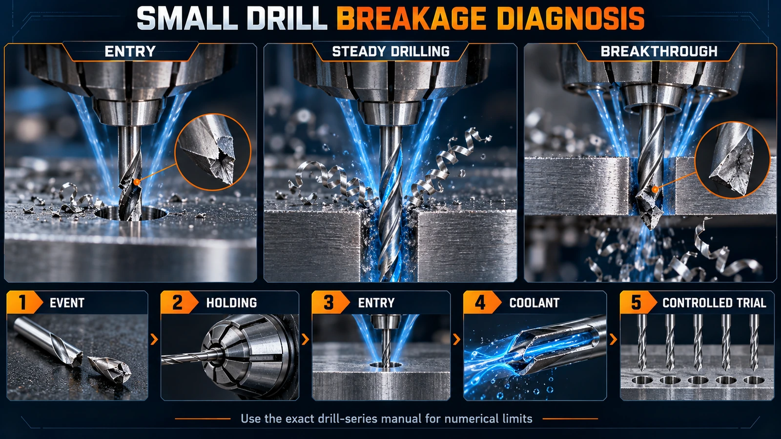
The broken piece alone rarely proves the root cause. Reconstruct the cycle and mark the stage at which the load changed.
| Failure stage | Evidence to collect | Checks to prioritize |
|---|---|---|
| During entry or pilot engagement | Entry surface, pilot geometry, cycle trace and first chips | Alignment, runout, unsupported edge contact and entry procedure |
| During steady drilling | Depth at failure, chip form, coolant state and spindle/feed trace | Chip packing, coolant delivery, material variation and tool wear |
| At a cross-hole or interrupted section | Part drawing, intersection position and fragment location | Loss of guidance, asymmetric cutting and supplier-approved strategy |
| At breakthrough | Exit surface, burr, remaining wall and feed change | Exit support, programmed feed and sudden load release |
| During retraction | Retraction position, packed chips and spindle state | Chip seizure, rubbing, coolant sequence and withdrawal procedure |
| During handling or setup | Tool photographs before use and change record | Collet damage, incorrect clamping, contact with the workpiece or operator handling |
Keep the failed tool, holder, workpiece and program revision together. Photograph the fracture without cleaning away chips that may help explain the event.
Wryno’s broader guide to drill breakage, burning and wear covers common failure families. The present article focuses on the smaller scale where setup and measurement capability become decisive.
Measure the toolholding system, not only the drill
Small tools amplify errors in the spindle–holder–collet–tool stack. Clean each interface using the manufacturer’s method and inspect the collet, nut, holder taper and shank. Replace damaged components rather than compensating with extra tightening.
Measure runout at the location specified by the tool or holder supplier. Record:
- spindle and holder identification;
- collet class, size and service condition;
- clamping length and tool overhang;
- measurement distance from the holder or cutting edge;
- static indicator result and, when available, dynamic behavior at operating speed;
- result after removing and reclamping the same tool.
BIG DAISHOWA’s microdrilling article emphasizes low dynamic runout, fine feed control, process stability and inspection when tools are changed. Its published page contains a suspicious unit conversion in one numerical example, so this guide deliberately does not repeat that figure. Apply the documented limit for the actual holder and drill system.
For a measurement sequence, use Wryno’s drill-bit runout and oversized-hole guide.
Check the entry and guidance method
A small drill should not be expected to correct a large positional or angular error while entering the workpiece. Confirm whether the specific tool series requires a pilot, spot, guide bushing or direct entry. If a pilot is specified, its diameter, angle, depth and alignment must match the manufacturer’s procedure.
Inspect these conditions:
- flat, angled, curved, rough or cast entry surface;
- distance from a free edge, cavity or previous hole;
- pilot runout and concentricity with the final drill;
- fixture rigidity and workpiece deflection;
- tool overhang and interference clearance;
- acceleration, entry feed and any dwell;
- whether the programmed cycle matches the tool’s length class.
Do not assume that pecking is safer. An unnecessary peck cycle can add time and repeated entry events, while a required chip-clearance cycle can prevent packing. Follow the drill-series guidance and validate the chips. Wryno’s peck drilling, coolant and chip evacuation guide explains the tradeoff.
Verify coolant flow and filtration at the tool
Pressure at a pump or gauge does not prove useful flow through a small drill. Check the complete path: tank condition, filtration, pump, rotary union, spindle, holder, sealing components and drill passages. Record the coolant type, concentration, temperature, pressure and observable flow under the actual configuration.
OSG’s published ADO-MICRO technical page is a good example of product-specific requirements. For that series, OSG specifies water-soluble coolant with internal supply, a 3–5 μm precision filter to reduce oil-hole blockage, and a recommended pressure of at least 3 MPa while instructing users to adjust for actual flow and coolant properties. These values belong to ADO-MICRO; they are not universal thresholds for every small drill.
Look for evidence of:
- clogged drill holes or contaminated filters;
- foam, aeration or unstable concentration;
- chips welded to the flute or margin;
- long, tangled or compacted chips;
- a change in coolant delivery after tool replacement;
- heat discoloration or deposits near the cutting edge.
Never test coolant flow in a way that exposes a person to a rotating tool or high-pressure fluid. Use the machine and tooling manufacturers’ inspection procedures.
Use a controlled breakage investigation
- Quarantine the evidence. Preserve the failed tool, matching workpiece, holder and program revision.
- Locate the event. Identify the cycle stage, depth and any alarm or load change.
- Inspect without destroying evidence. Photograph chips, buildup and fracture position before cleaning.
- Check the machine and holder. Verify interface condition, clamping, overhang and runout using a documented method.
- Verify entry and alignment. Confirm pilot, surface condition, fixturing and tool path.
- Verify coolant and chips. Record filtration, delivery, concentration and chip form.
- Compare with the exact tool manual. Check material group, length class, speed, feed, cycle and coolant requirements.
- Change one factor and trial at low exposure. Use a controlled first-piece plan rather than returning directly to full production.
- Inspect the first successful holes. Measure size, position, straightness or other drawing requirements and inspect the tool before expanding the trial.
Avoid fitting a new drill and changing speed, feed, holder and coolant at the same time. That may restore production temporarily but destroys the evidence needed to prevent recurrence.
First-piece acceptance record
| Record group | Minimum useful fields |
|---|---|
| Workpiece | Material specification, hardness/condition, lot, entry/exit geometry and hole depth |
| Tool | Manufacturer, series, diameter, length class, coating, lot and previous use |
| Holding | Holder, collet, overhang, clamping method and measured runout location/result |
| Machine | Spindle, program revision, speed, feed, entry/exit and cycle details |
| Coolant | Type, concentration, temperature, filtration, pressure/flow evidence and delivery path |
| Result | Hole measurements, chip form, tool condition, alarms, images and operator/time |
The record should distinguish a supplier’s catalog recommendation from the buyer’s measured result.
RFQ and failure-report checklist
Send the tool supplier:
- actual drill diameter and total depth, expressed also as L/D;
- blind or through hole, pilot, cross-hole, angled entry or exit;
- workpiece material, condition and lot;
- machine, spindle interface and available speed/feed resolution;
- holder, collet, tool overhang and runout record;
- coolant type, internal/external delivery, filtration and available pressure/flow evidence;
- current cycle and tool-series instructions used;
- failure stage, depth, fracture photographs and chip photographs;
- hole-quality results before and after failure;
- sample quantity and acceptance criteria.
A clear failure report is more useful than asking for “a stronger micro drill” without process data.
FAQ
Why do small carbide drills break suddenly?
Carbide drills can fail abruptly when bending, runout, chip packing, unstable entry or coolant loss raises the load beyond the small cross-section’s capacity. The fracture appearance alone may not identify which condition started the event.
What runout limit should be used for a micro drill?
Use the limit and measurement position documented for the exact drill, holder and application. A single internet value should not be treated as universal. Also distinguish static indicator results from dynamic behavior at operating speed.
Is high coolant pressure always better?
No. The tool’s passages, coolant properties, filtration, machine and seals determine useful flow and safe limits. OSG’s 3 MPa recommendation is for its ADO-MICRO series under stated conditions, not every drill.
Should a small drill always use peck drilling?
No. Some tools and applications are designed for continuous drilling; others need step or chip-clearance cycles. Follow the exact series guidance and validate chip evacuation.
What evidence should be kept after a breakage?
Keep the failed tool and fragments, workpiece, holder, program revision, cycle stage, chips, coolant record, runout measurement and photographs. Do not clean or discard the evidence before recording it.