
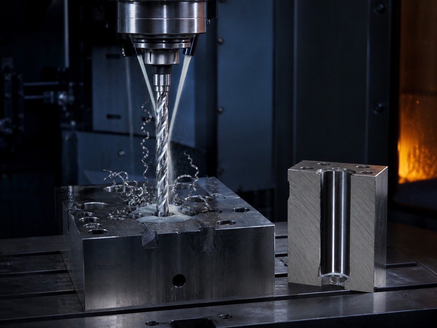
Deep-hole drilling failures are often chip-management failures. As
depth increases, chips travel farther, coolant access becomes more
difficult and the drill is more likely to rub, deflect or seize. A
reliable process combines the correct drill geometry, minimum necessary
projection, feed, peck cycle and coolant delivery.
Classify the hole
by depth-to-diameter ratio
| Depth ratio | General process concern |
|---|---|
| Up to 3×D | Conventional drilling often works with normal chip control |
| 3–5×D | Pecking and coolant access become more important |
| 5–10×D | Deep-hole geometry, stable evacuation and low runout required |
| Above 10×D | Consider through-coolant drills, gun drilling or specialist process |
These are starting categories, not universal limits. Small diameters
and gummy materials become difficult earlier.
What peck drilling does
A peck cycle interrupts axial travel so chips can break and leave the
flute. The drill may retract fully, partially or only enough to unload
the cutting edge. Excessive full retraction wastes cycle time and can
shock the edge on re-entry; too little retraction leaves packed chips in
place.
| Peck style | Use | Risk |
|---|---|---|
| Full retract | Difficult chips, poor coolant access | Slow cycle and repeated re-entry |
| Partial retract | General CNC deep holes | Must clear enough chip volume |
| Micro-peck | Small drills and controlled chip breaking | Can rub if feed is too low |
| No peck, through-coolant | Optimized production tooling | Requires reliable coolant and chip path |
Select peck depth from
chip behavior
Do not choose peck depth only from a generic multiple. Observe chip
length, flute fill, spindle load and coolant return. Ductile stainless
and aluminum may make long chips that require more frequent unloading.
Cast iron makes short chips but abrasive dust can still damage
margins.
Coolant delivery
Coolant must reach the cutting edge and carry heat and chips out.
Flood coolant may be adequate for shallow holes, while through-tool
coolant is more reliable at higher depth ratios. Pressure, flow,
filtration and nozzle direction all matter.
| Coolant method | Strength | Limitation |
|---|---|---|
| Cutting oil | Lubricity for HSS/cobalt | Heat removal and chip flushing may be limited |
| Emulsion flood | Cooling and general flushing | May not reach deep cutting zone |
| Through-tool coolant | Direct edge cooling and chip transport | Requires compatible drill, holder and filtration |
| Air/mist | Useful in selected non-ferrous/dry setups | Must manage safety, heat and chip evacuation |
Drill geometry for deep
holes
Use sufficient flute volume, a stable core, smooth margins and an
accurate point. Polished flutes help prevent aluminum chips from
welding. Stainless needs a point that cuts positively without rubbing.
Through-coolant holes must be unobstructed and correctly aligned.
Tool length and runout
Use the shortest drill and holder projection that reaches the hole.
Long projection magnifies runout and deflection. Measure the system near
the point, not only at the shank. A small error at the holder becomes a
larger sweep at the cutting edge.
Feed and speed strategy
Feed must be high enough for the lips to cut, not rub. Reduce cutting
speed as necessary for heat and depth, but do not compensate for chip
packing by lowering feed to nearly zero. On re-entry after a peck, avoid
impacting trapped chips at full feed.
| Symptom | Parameter/process response |
|---|---|
| Blue chips and burned corners | Reduce speed, improve coolant |
| Long string chips | Adjust feed, geometry or peck frequency |
| Powder/fines and squeal | Increase effective chip load; inspect dull point |
| Rising spindle load with depth | Retract and clear; review flute capacity |
Material-specific
starting considerations
| Workpiece | Main risk | Process emphasis |
|---|---|---|
| Aluminum | Chip welding and long soft chips | Polished flute, ample space, anti-adhesion coolant |
| Mild steel | Heat and chip accumulation | Balanced peck and emulsion/oil |
| Stainless steel | Work hardening and stringy chips | Positive feed, cobalt/carbide, strong coolant |
| Cast iron | Abrasive dust | Wear-resistant tool, filtration/extraction |
| Hardened steel | Edge chipping and heat | Rigid carbide process, low runout, engineered coolant |
Entry, pilot and breakthrough
A pilot or spot should guide the drill without forcing its corners
into a mismatched cone. For through-holes, reduce instability at
breakthrough with backing support, controlled feed or a dedicated cycle.
Blind-hole depth must account for the drill-point length.
Troubleshooting deep-hole
failures
| Failure | Likely cause | Corrective action |
|---|---|---|
| Drill seizes | Packed chips, insufficient coolant | Clear flutes, shorten peck, improve flow |
| Breakage after several depths | Heat accumulation, runout, re-entry shock | Inspect cycle, projection, holder and coolant |
| Hole wanders | Deflection, poor entry, long projection | Spot correctly, shorten setup, use guided geometry |
| Poor finish near bottom | Chip recutting or worn margins | Improve evacuation and inspect body wear |
| Oversize entrance | Walking or runout | Improve spotting and concentricity |
Through-coolant system
checks
Verify coolant-hole diameter and position, holder seals, pump
pressure under flow, filter rating and actual outlet flow. Static pump
pressure without flow is not enough. Inspect for coating or debris
blocking the drill’s internal channels.
Process validation
Record drill lot, holder, measured TIR, workpiece batch/hardness,
depth ratio, speed, feed, peck amount, retract distance, dwell, coolant
concentration/pressure and number of acceptable holes. Change one
variable at a time.
RFQ checklist for deep-hole
drills
Provide diameter, total/flute length, required depth, tolerance,
blind/through hole, workpiece and hardness, machine spindle/holder,
coolant type and pressure, expected volume and failure history. Ask the
supplier to state recommended starting data and reconditioning
limits.
FAQ
How often should a drill
peck?
Set the interval from chip volume and material behavior. Reduce the
interval if load rises or chips pack; avoid unnecessary full
retractions.
Is through-coolant
always necessary above 5×D?
Not always, but it becomes increasingly valuable. Diameter, material,
geometry and production target determine the requirement.
Why does a drill
break only near full depth?
Heat and chip volume accumulate with depth. Packed chips, deflection
and coolant starvation commonly appear late in the cycle.
Should feed be reduced
for a deep hole?
Sometimes, but not until the drill rubs. Maintain enough chip load
for positive cutting and manage heat through speed, coolant and peck
strategy.
ENGINEERING KNOWLEDGE
Related Drill Bit Engineering Guides
Continue from product type into geometry, coating, hole quality, regrinding and deep-hole process control.