
A magnetic drill is a system, not a motor sold separately from a cutter. The machine, magnet, arbor, pilot pin, cutter geometry, workpiece thickness and coolant path must work together. Buyers who compare only rated diameter or wattage can end up with a tool that cannot hold safely, reach the joint, eject the slug or maintain tool life on the actual structure.
Start with the hole and the structure
Define hole diameter, finished tolerance, depth, whether the hole is through or blind, the steel grade, plate thickness, surface condition and available access. A nominal 26 mm through-hole in clean flat plate is a different job from a deep hole near a welded stiffener, on a painted beam or in a vertical position.
| Application question | Why it changes the choice | Buyer evidence |
|---|---|---|
| Maximum diameter and depth | Sets motor load, stroke and cutter series | Drawing plus worst-case hole list |
| Flat, curved or coated surface | Changes magnetic contact and holding stability | Photos and minimum contact area |
| Horizontal, vertical or overhead | Changes restraint, coolant delivery and operator exposure | Work method and secondary retention plan |
| Space around the hole | May require a low-profile machine or short arbor | Envelope dimensions around the centreline |
HSS, carbide-tipped and solid-carbide annular cutters
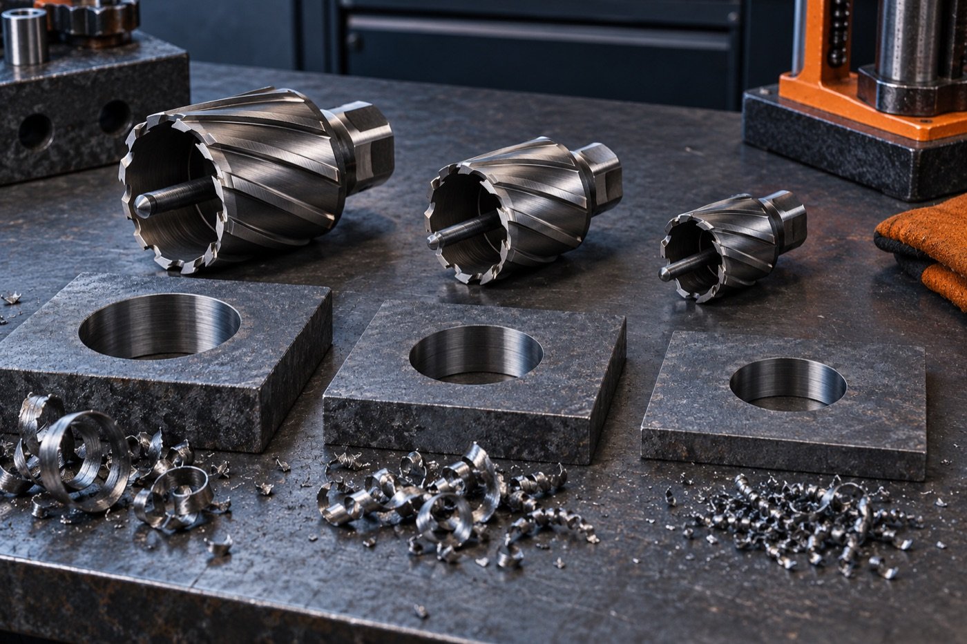
HSS cutters are generally tolerant and economical for mixed maintenance work. Carbide-tipped cutters can improve productivity on harder or abrasive material when the machine and setup are stable. Solid-carbide designs are more specialised and should not be selected only because carbide sounds premium. Ask for the intended material range, cutting-speed window, resharpening policy and failure limits.
Confirm arbor and shank compatibility
Common cutter systems are not automatically interchangeable. Record shank diameter and flat arrangement, arbor type, pilot-pin series, coolant feed, maximum cutter length and the machine’s spindle interface. A cutter that physically enters an arbor can still be wrong if the drive flats, pilot length or coolant passage do not match.
Magnet holding is an application condition
Published magnetic force is normally obtained under defined conditions. Thin plate, scale, rust, paint, curvature, a gap or a small contact footprint can reduce real holding. The procurement specification should require the manufacturer’s minimum workpiece thickness and surface conditions, not convert a headline holding-force number into a universal guarantee.
Motor, gears and electronic protection
Compare usable speed ranges at the cutter diameters you will run. Large cutters generally need lower speed and high torque; small cutters may need higher speed to work efficiently. Useful machine features can include mechanical gearing, overload protection, restart prevention, speed feedback and a visible magnet-status indicator. Confirm what happens after a power interruption and whether the machine can restart unexpectedly.
Coolant, chip flow and slug ejection
Coolant must reach the cutting edge, not merely wet the machine. The pilot pin should suit the cutter depth and support slug ejection. For vertical or overhead work, the supplier should state the approved lubrication method. Repeated blue chips, welded chips, broken corners or stuck slugs indicate that the setup or operating window needs correction before a harder cutter is ordered.
Mag-drill RFQ checklist
- Hole diameter range, quantity and maximum depth.
- Steel grade, hardness if known, plate thickness and surface coating.
- Working position, available clearance and minimum magnet contact area.
- Voltage, duty cycle, required speeds and site power constraints.
- Arbor, shank, pilot pin and coolant system.
- Secondary retention, carrying case, guard and required documentation.
- Replacement parts, service location and cutter resharpening options.
Acceptance test before fleet purchase
Test the largest and most difficult hole on representative steel. Record setup time, magnet condition, drilling time, cutter temperature, chip form, slug release, hole size, burr and cutter wear. A fleet decision should be based on repeatable holes per cutter and controllable setup—not one demonstration hole made under ideal conditions.