
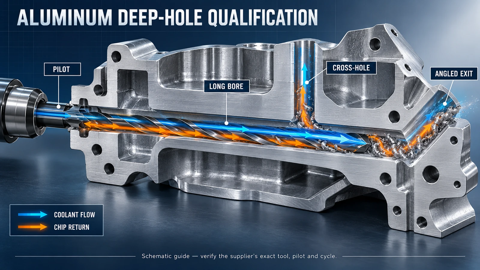
A deep hole in aluminum can look straightforward on a drawing while presenting several different cutting conditions inside the part. The drill may start in a pilot, pass through a cross-hole and exit an angled surface. Each transition changes guidance, cutting engagement and chip behavior.
For buyers, the key question is not simply whether a supplier offers a “40D drill.” The process must match the actual alloy, hole geometry, machine, coolant delivery and acceptance criteria. This guide provides an RFQ and qualification framework for those decisions.
Scope: Product ranges and performance claims cited from MAPAL describe its second-generation MEGA-Deep-Drill-Alu. They are examples of a manufacturer-specific solution, not Wryno test results or universal drilling capability.
Translate the drawing into drilling events
Mark every change along the tool path before requesting a quotation.
| Drawing feature | Process question | Evidence required in a trial |
|---|---|---|
| Pilot or guide bore | What pilot geometry, diameter and depth does the tool system require? | Pilot inspection and concentricity record |
| Long uninterrupted section | Can chips and coolant travel reliably over the full depth? | Chip form, coolant evidence and bore measurements by depth |
| Cross-hole or cavity | How will the tool be supported as one cutting edge loses engagement? | Cycle position, load behavior and condition after the intersection |
| Angled or curved exit | How will asymmetric breakthrough affect guidance and burrs? | Exit photographs, burr measurement and tool inspection |
| Blind bottom | Where do chips collect, and what clearance remains? | Actual depth, bottom condition and chip-removal record |
| Thin wall or interrupted feature | Can the part deflect or the drill grab? | Fixture method, wall condition and dimensional result |
Do not hide cross-holes or angled exits inside a generic “deep-hole” description. They can change the recommended drill, pilot and cycle.
For an overview of process routes, compare Wryno’s BTA, gun drilling and peck drilling guide.
Specify the aluminum alloy and condition
“Aluminum” is not enough. Provide the alloy designation, temper or casting condition, silicon content where relevant, surface condition and lot. Wrought alloys and high-silicon cast alloys can present different adhesion, abrasion and chip-control challenges.
MAPAL states that its second-generation MEGA-Deep-Drill-Alu range addresses wrought alloys through high-silicon cast alloys with configurable coatings. That is a product claim and selection example. A buyer still needs the specific tool recommendation and a representative-material trial.
If coating and adhesion are part of the comparison, Wryno’s DLC-coated drill-head guide for aluminum and copper explains why coating, geometry, polishing and coolant must be evaluated together.
Qualify the machine and coolant path
Record the machine spindle, holder interface, available speed and feed, maximum usable tool length, runout method and fixture. Then document the coolant system from tank to cutting edge:
- coolant or MQL type and concentration;
- pressure and, where possible, flow under the actual tool configuration;
- filtration and temperature control;
- rotary union, holder and seal compatibility;
- internal-channel availability and cleanliness;
- how the cycle switches coolant on and off during entry and retraction;
- chip return path and signs of recutting or packing.
Machine nameplate pressure does not prove adequate flow at the tool tip. Conversely, a larger pump setting is not automatically safe for the seals, holder or tool. Use the limits specified by the equipment and tool manufacturers.
MAPAL attributes part of its product’s performance to redesigned internal coolant channels, guidance and chip evacuation. Treat that as a prompt to verify the complete coolant path, not as a reason to copy a catalog feed into an unqualified machine.
Match the drill and pilot as a system
Ask the supplier to specify:
- drill family, diameter, length class and cutting material;
- coating option for the stated alloy and coolant strategy;
- pilot or guide tool, including diameter relationship and point geometry;
- holder, clamping length and maximum runout requirement;
- entry, acceleration, full-depth and retraction sequence;
- whether chip-clearance cycles are required;
- instructions for cross-holes, interrupted cuts and angled exits;
- coolant pressure/flow and filtration requirements;
- reconditioning, inspection and replacement limits.
Do not combine a pilot from one system with a deep drill from another without written compatibility evidence. The interface between the pilot and long drill affects guidance at the moment when the deep drill is least supported.
The peck drilling, coolant and chip evacuation guide provides a broader checklist for chip-control decisions.
Treat published performance as a product-specific reference
MAPAL’s current public pages describe second-generation MEGA-Deep-Drill-Alu lengths of 15×D, 20×D, 25×D, 30×D and 40×D. A related MAPAL announcement reports a 3–16 mm range and cites high-feed field results. These figures describe that named product and its stated test context; they do not establish a universal capability for every aluminum part, drill or supplier.
When reviewing a manufacturer claim, request:
- exact tool code and diameter;
- alloy and workpiece geometry;
- machine, holder and coolant setup;
- pilot and cycle;
- sample size and stopping criterion;
- measurements, tool inspection and rejected holes;
- whether the result is a catalog recommendation, field trial or independently reproduced test.
Avoid turning a maximum feed or total drilled distance into an acceptance guarantee. Use it to design a representative trial.
Build a staged qualification trial
Stage 1: setup and pilot
Verify the workholding, datum, pilot geometry, alignment, holder and runout. Measure the pilot before using an expensive long drill.
Stage 2: uncomplicated reference hole
Where possible, establish chip form, coolant behavior and bore quality in a representative section without an intersection. This separates basic setup problems from cross-hole effects.
Stage 3: cross-hole and angled exit
Run the most difficult geometry under controlled conditions. Record load changes, chip behavior, burrs and the tool condition immediately after each transition.
Stage 4: repeatability
Produce enough holes to see whether size, straightness, finish and burrs remain stable. Include more than one part or material lot when the production risk justifies it.
Stage 5: cost per accepted hole
Add tool cost, pilot cost, cycle time, inspection, rejected parts, machine interruptions, reconditioning and tool-change time. Report accepted holes, not only completed cycles.
Hole acceptance record
| Category | Possible requirement to define |
|---|---|
| Geometry | Diameter, cylindricity/roundness where required, position, straightness and depth |
| Surface | Roughness or functional surface requirement at specified locations |
| Intersections | Cross-hole edge, breakout, burr and evidence of material tearing |
| Exit | Burr height/condition, chipping and local deformation at the angled surface |
| Process | Cycle time, alarms, coolant behavior, chip form and interruptions |
| Tool | Wear, buildup, edge damage, margin condition and reconditioning decision |
Use drawing-specific tolerances. Do not invent one “deep-hole tolerance” for every application.
RFQ checklist
- part drawing with the full tool path and all intersections;
- hole diameter, total depth and L/D ratio;
- pilot, cross-holes, cavities, angled entry or angled exit;
- aluminum alloy, temper/cast condition, silicon content and lot information;
- machine, spindle, holder, maximum tool length and runout capability;
- coolant/MQL type, filtration, pressure and available flow evidence;
- required diameter, position, straightness, surface and burr limits;
- planned inspection method and sample size;
- current process, failure mode and chip photographs;
- production volume, changeover frequency and cost target;
- request for the exact tool, pilot, cycle and reconditioning proposal.
The RFQ should allow the supplier to identify missing information instead of assuming the easiest geometry.
FAQ
Does 40×D mean the drill can handle every 40×D aluminum hole?
No. It describes a length class in a specific product range. Alloy, diameter, intersections, machine, pilot, holder, coolant and acceptance criteria still need qualification.
Why are cross-holes difficult in deep drilling?
At an intersection, cutting engagement and guidance can change suddenly. Chips may also enter the cavity or recirculate. The drill and cycle must be approved for that geometry.
What changes at an angled exit?
One side of the cutting edge can break through before the other, creating asymmetric forces, burrs and possible deflection. Inspect the exit and the tool rather than measuring only the main bore diameter.
Is coolant pressure enough to qualify the process?
No. Useful flow at the cutting edge, filtration, channel size, coolant properties, temperature, seals and chip return all matter. Record the actual configuration.
Should the trial use the easiest hole first?
An uncomplicated reference hole can help isolate basic setup issues, but final approval must include the most difficult representative cross-hole, angled exit and production conditions.