
Choosing between a 118-degree and a 135-degree drill point is not
simply a choice between “general purpose” and “hard metal.” The correct
point must match the workpiece, drill diameter, machine rigidity, feed
method and hole requirement. This guide gives buyers and production
engineers a practical starting point, while making clear where a cutting
trial is still required.
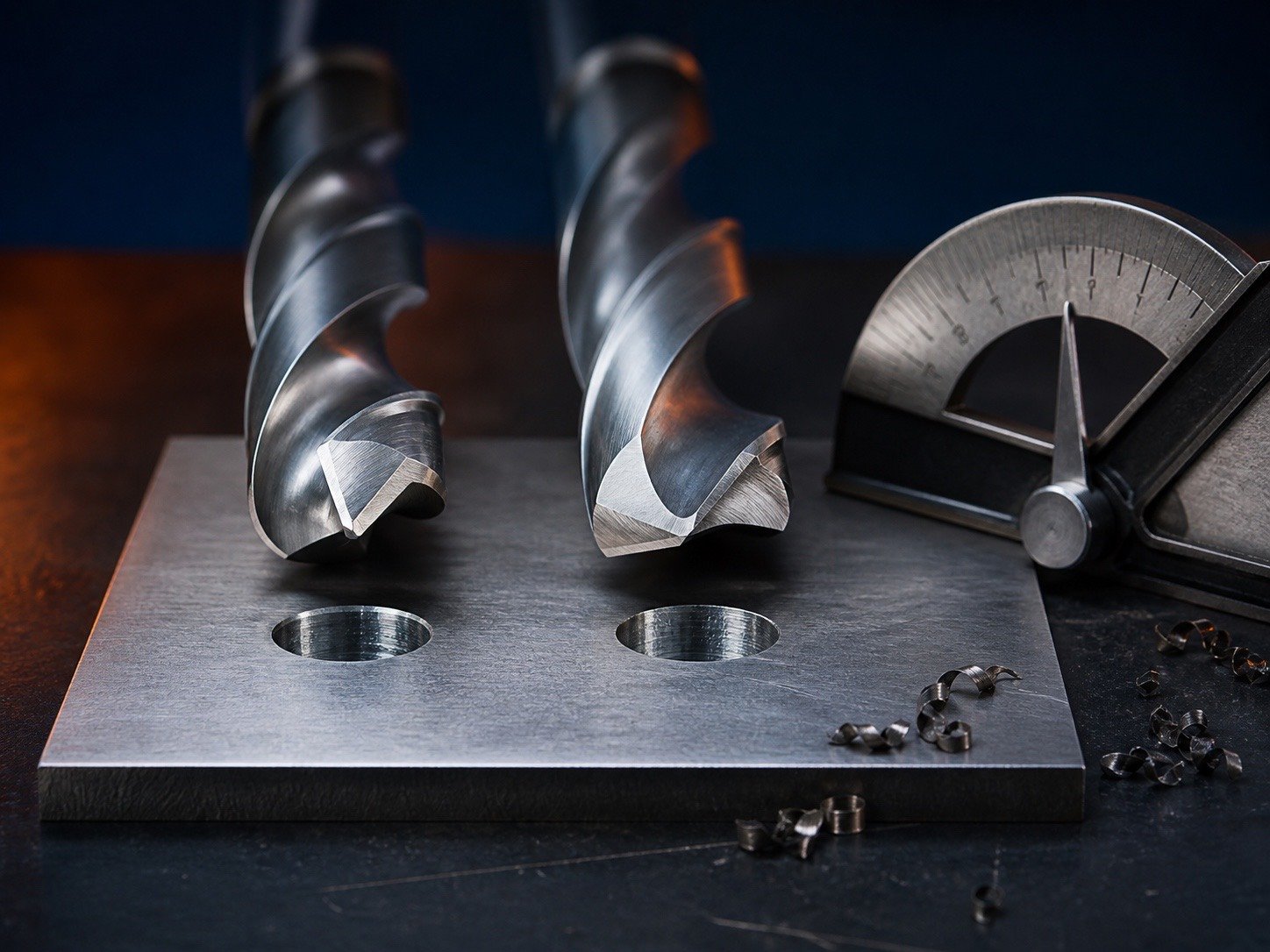
Quick answer: 118° or 135°?
| Starting condition | Usually start with | Why |
|---|---|---|
| Mild steel, aluminum, wood, plastic and hand-fed general work | 118° | Lower thrust and easy entry in many softer materials |
| Stainless steel, alloy steel and harder stock | 135° split point | Shorter chisel edge, stronger point and less walking |
| Thin sheet where exit burr matters | 135° split point or step drill | Better centering; the exact result depends on feed and support |
| Flexible drill press or hand drill | 118° or robust 135° geometry | Avoid brittle, overly aggressive geometry |
| CNC production with rigid workholding | Application-specific 135°/140° geometry |
Higher repeatability and better control of chip load |
The angle is only one part of the point. A poorly ground 135° point
can perform worse than a concentric 118° point with equal lips.
What the point angle changes
The included angle changes the length of each cutting lip, the
thickness of material beneath the edge and the axial force required to
enter the workpiece. A flatter point generally has a shorter chisel edge
and stronger cutting edge. A sharper point enters with less axial
contact but can have less edge support.
| Effect | 118° point | 135° point |
|---|---|---|
| Point profile | More pointed | Flatter |
| Typical thrust | Often lower in softer material | Can require firm, controlled feed |
| Edge support | Moderate | Stronger near the point |
| Walking resistance | Fair; center punch may help | Better when correctly split |
| Typical use | General-purpose drilling | Tougher alloys and production work |
How a 118° drill behaves
A conventional 118° point is common on general-purpose HSS drills. It
works well when the workpiece is not very hard, the operator needs easy
entry, and the machine does not provide high thrust. It is also easy for
many shops to resharpen consistently.
Its limitations appear when the material work-hardens, the surface is
curved or the hole must begin without a pilot. A large unsplit chisel
edge can rub before the cutting lips engage. If the operator hesitates,
stainless steel can harden locally and rapidly damage the drill.
How a 135° split point
behaves
A 135° split point reduces the effective chisel edge and creates
additional cutting facets near the center. This improves self-centering
and reduces the tendency to skate across a smooth surface. The flatter
point also provides more support behind the cutting edge.
Split-point quality must be inspected. The split facets should be
symmetrical and should meet close to the drill axis. If one lip is
longer or one split is deeper, the drill can cut oversize, create a
bell-mouthed entrance or load one corner until it chips.
Choose by workpiece material
| Workpiece | Practical starting point | Additional requirement |
|---|---|---|
| Aluminum alloys | 118°–130°, polished flute | Prevent built-up edge; use adequate chip space |
| Low-carbon steel | 118° or 135° | Select by machine, hole depth and productivity target |
| Stainless steel | 135° split point | Positive feed, low runout and suitable coolant |
| Hardened steel | 135°–140° carbide geometry | Verify hardness and machine rigidity first |
| Brass and copper | Controlled-rake geometry | Prevent grabbing; angle alone is insufficient |
| Plastics | Sharp, low-heat geometry | Support the exit and avoid melting |
Diameter and hole depth
matter
Small drills have a relatively thick chisel edge compared with their
diameter, so web thinning and point symmetry become especially
important. Larger drills create higher torque and more chip volume. For
holes deeper than roughly three drill diameters, chip evacuation and
coolant delivery can dominate the result more than the nominal point
angle.
| Hole condition | Geometry priority |
|---|---|
| Shallow through-hole | Point angle, exit support and burr control |
| Blind hole | Point length, usable depth and bottom profile |
| Deep hole | Flute volume, coolant access and peck strategy |
| Curved surface | Split point, spotting and workholding |
Match the point to the
machine
A hand drill, bench drill and machining center do not hold the tool
with the same rigidity. Carbide and aggressive split points need stable
holders and controlled feed. On a flexible machine, a tougher cobalt
drill may survive interrupted contact better than a brittle carbide
tool, even if carbide is faster in a rigid CNC setup.
Check spindle runout, chuck condition, holder projection and
workpiece clamping before blaming the angle. Point geometry cannot
compensate for a drill rotating eccentrically.
Feed, speed and coolant
Do not reduce feed until the drill only rubs. Each cutting lip needs
enough chip load to cut beneath the work-hardened surface. Set
rotational speed from drill diameter, tool substrate, coating and
workpiece—not from point angle alone. Use cutting oil or a validated
coolant process for stainless and alloy steel; keep aluminum chips from
welding to the flute.
Failure diagnosis
| Symptom | Likely cause | Corrective action |
|---|---|---|
| Drill walks at entry | Unsplit point, curved surface, excessive runout | Spot, use a correct split point, inspect holder |
| One lip wears first | Unequal lips or runout | Regrind symmetrically; measure TIR |
| Blue/burned point | Excess speed, rubbing, poor coolant | Reduce speed, restore feed and coolant |
| Oversized hole | Point asymmetry, runout or unstable setup | Inspect drill, chuck, spindle and clamping |
| Chipped corners | Excess feed, interrupted cut or brittle tool | Stabilize entry; select tougher substrate/geometry |
How buyers should
specify point geometry
An RFQ should state diameter range, length, substrate (HSS, M35, M42
or carbide), coating, point angle, split-point requirement, workpiece
material and hardness, hole depth, machine type and target hole
tolerance. “135° drill” alone does not define the lip relief, web
thinning or acceptable point concentricity.
Incoming inspection
checklist
| Check | What to verify |
|---|---|
| Point angle | Within the agreed drawing tolerance |
| Lip length | Both lips equal within the agreed limit |
| Chisel/split | Symmetrical and centered |
| Runout | Measured at a defined distance from the holder |
| Surface finish | No burns, grinding cracks or coating buildup |
| Trial holes | Diameter, roundness, burr, surface and tool life |
Recommended decision process
Start with workpiece hardness and machine rigidity, then choose
substrate and point style. Confirm with a controlled trial using
recorded speed, feed, coolant and hole depth. Compare cost per
acceptable hole rather than purchase price per drill.
FAQ
Is 135° always better than
118°?
No. It is often better for harder alloys and self-centering, but a
118° point can be easier to feed in softer materials and flexible
equipment.
Does a 135° point need a
pilot hole?
A correctly made split point often starts without a pilot on a flat
surface, but curved, scaled or critical surfaces may still require
spotting.
Can a 118° drill be reground
to 135°?
Often yes if enough material remains, but the web and relief must
also be corrected. The finished tool should be inspected and
trialed.
Which angle is best for
stainless steel?
A 135° split point is a strong starting choice, combined with cobalt
or suitable carbide, positive feed, low runout and adequate coolant.
ENGINEERING KNOWLEDGE
Related Drill Bit Engineering Guides
Continue from product type into geometry, coating, hole quality, regrinding and deep-hole process control.