
Two drills with the same diameter, material and coating can produce
very different results because their geometry differs. Point shape
controls entry, web thickness affects thrust, flute form controls chip
evacuation, and lands/margins guide the drill in the hole. This guide
helps buyers translate an application into measurable geometry
requirements.
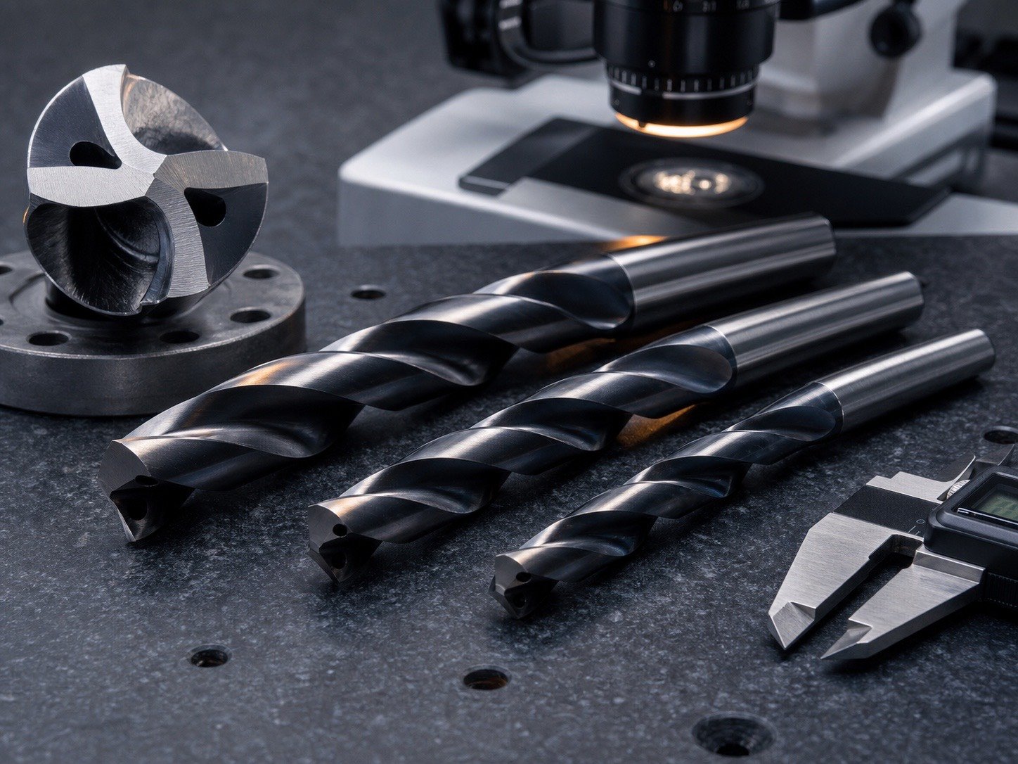
Geometry overview
| Feature | Primary function | If incorrect |
|---|---|---|
| Point angle | Entry, edge support and chip initiation | Walking, high thrust or corner chipping |
| Cutting lips | Remove material | Oversize hole if unequal |
| Chisel edge/web | Supports core and crosses center | Excess thrust if too thick |
| Flutes | Form and evacuate chips | Packing, heat and breakage |
| Helix angle | Influences rake and chip flow | Grabbing or poor evacuation |
| Lands/margins | Guide and size the hole | Rubbing, poor roundness or instability |
| Core taper | Balances rigidity and chip space | Weak shank or restricted flute volume |
Point angle and point style
Common points include 118° general-purpose points, 135° split points
and application-specific carbide geometries. The included angle should
be specified together with lip relief, chisel length, split style and
point concentricity.
| Point style | Typical advantage | Typical use |
|---|---|---|
| Conventional 118° | Easy general-purpose entry | Mild steel, aluminum and mixed shop work |
| 135° split point | Better centering and stronger point | Stainless and alloy steel |
| Four-facet point | Accurate centering and controlled chisel | Precision production and regrinding |
| Special flat/bottom point | Defined bottom geometry | Counterbores and application-specific holes |
Cutting lips and lip relief
The two main lips should have equal length and angle. If one lip is
longer, it carries more load and the drill behaves as if it were larger.
Relief behind the cutting edge prevents rubbing, but too much relief
weakens the edge.
Inspect lips under magnification. Compare length, edge condition and
corner radius. A good-looking point can still be off-center by enough to
reduce hole quality.
Web thickness and chisel
edge
The web is the central core between the flutes. A thicker web
increases torsional strength but also makes a longer chisel edge, which
pushes rather than cuts at the center. Web thinning or a split point
reduces thrust.
| Web condition | Benefit | Risk |
|---|---|---|
| Thin web | Lower thrust, more flute volume | Lower core strength |
| Thick web | Greater rigidity and torque capacity | Higher thrust and heat at center |
| Tapered core | Strength increases toward shank | Must be controlled consistently |
Flute form and chip space
Flute cross-section determines chip capacity and coolant access.
Wide, polished flutes help aluminum chips escape. Stronger cores and
controlled flute shapes are useful for stainless, alloy steel and
interrupted cuts. Deep holes require enough space for accumulated chip
volume.
Helix angle
A higher helix generally increases rake and assists chip lifting,
while a lower helix can provide a stronger edge and less grabbing. The
correct value depends on ductility, chip length, wall thickness and
machine stability.
| Material/condition | Typical helix direction |
|---|---|
| Aluminum and soft ductile alloys | Higher helix, polished flute |
| General steel | Standard helix |
| Brass and grabbing materials | Lower/controlled helix |
| Hardened or abrasive material | Strong edge, application-specific helix |
Lands and margins
The land is the outside portion remaining between flutes; the margin
is the narrow strip that contacts and guides the hole. Wide margins
improve guidance but increase friction. Narrow or double margins can
control friction and roundness differently.
Margin diameter, back taper and surface finish should be included
when tight hole tolerance or deep-hole guidance matters.
Back taper and body
clearance
A drill is often slightly smaller toward the shank so the body does
not rub continuously. Too little clearance generates heat; too much can
reduce guidance. Measure diameter at defined axial positions rather than
describing the drill simply as “accurate.”
Choose geometry by workpiece
| Workpiece | Geometry priorities |
|---|---|
| Aluminum profile/sheet | Sharp edge, polished flute, ample chip space |
| Mild steel | Balanced standard geometry |
| Stainless steel | Split point, strong edge, positive cutting action |
| Hardened steel | Rigid carbide geometry, edge preparation, low runout |
| Brass/copper | Anti-grab rake and controlled helix |
| Plastics | Sharp edge, low heat and clean exit support |
Diameter, length and hole
depth
As drill diameter decreases, point symmetry and web control become
more sensitive. As length increases, deflection and runout increase.
Specify flute length and overall length only as long as needed; excess
projection lowers rigidity.
| Hole depth ratio | Main concern |
|---|---|
| Up to 3×D | Entry, point and general chip flow |
| 3–5×D | Peck strategy and coolant access |
| 5–10×D | Dedicated deep-hole geometry and stable evacuation |
| Above 10×D | Application engineering, through-coolant or gun-drill process |
Inspection and measurement
Use an optical comparator or tool measuring system for point angle,
lip length and profile. Measure diameter, margin, back taper and runout
with calibrated equipment. Record the distance from the holder at which
runout is measured.
Failure diagnosis by
geometry
| Symptom | Geometry-related cause | Check |
|---|---|---|
| High thrust | Thick web, insufficient relief, dull edge | Chisel length and relief |
| Oversized hole | Unequal lips, runout, poor margins | Point concentricity and TIR |
| Chip packing | Insufficient flute volume or wrong helix | Flute form and peck cycle |
| Grabbing at breakthrough | Excess rake/helix or poor support | Exit support and geometry |
| Corner chipping | Weak edge or unstable entry | Edge prep, point and holder |
RFQ and drawing checklist
State diameter tolerance, overall/flute length, shank, substrate,
coating, point angle and style, lip relief, web-thinning requirement,
helix direction/range, margin configuration, back taper,
workpiece/hardness, hole depth and machine/coolant conditions. Approve a
measured sample and trial holes before mass production.
FAQ
What part of
a twist drill actually sizes the hole?
The cutting lips create the hole and the margins guide the drill near
nominal diameter. Runout and unequal lips can still make the hole
oversize.
Does a thicker
web always make a stronger drill?
It increases core strength but also raises thrust unless the web is
thinned or split correctly.
What helix angle is best
for aluminum?
A higher helix with polished flute is a common starting point, but
wall thickness, chip form and machine feed still matter.
Why specify back taper?
It prevents the drill body from rubbing while maintaining enough
guidance for hole quality.
ENGINEERING KNOWLEDGE
Related Drill Bit Engineering Guides
Continue from product type into geometry, coating, hole quality, regrinding and deep-hole process control.