
When a drilled hole is oversize, out of round or bell-mouthed, the
drill is only one possible cause. The complete rotating system includes
spindle bearings, taper, holder, collet or chuck, drill shank, point
geometry and workpiece clamping. Runout diagnosis must separate these
contributors instead of replacing drills at random.
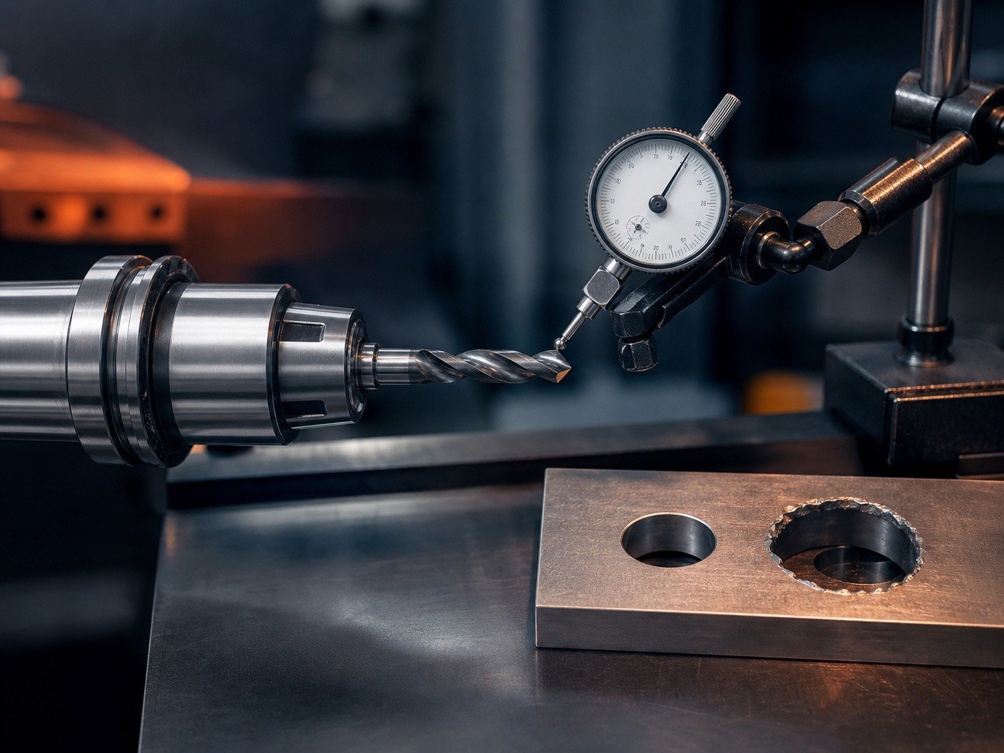
What is drill runout?
Runout is the deviation of a rotating surface from the intended axis.
It is commonly reported as total indicator reading (TIR). A reading
taken at the shank and a reading taken near the drill point describe
different parts of the system; always record the measurement
location.
| Measurement | What it helps identify |
|---|---|
| Spindle taper | Machine baseline |
| Holder taper/body | Holder seating and damage |
| Collet/chuck near nose | Clamping concentricity |
| Drill shank | Shank straightness and clamping |
| Near drill point | Accumulated system error and tool deflection |
Why runout enlarges holes
An eccentric drill sweeps a larger path. One lip may carry most of
the chip load while the opposite lip rubs. This accelerates asymmetric
wear, increases vibration and can create a triangular or multi-lobed
profile rather than a round hole.
Runout also changes coolant and chip flow. The heavily loaded lip may
chip first, after which hole size becomes even less stable.
Runout is not the
same as hole-size error
Hole size is influenced by drill geometry, material springback, heat,
feed, tool wear and measurement method. A drill can have low static TIR
and still deflect in the cut. Conversely, a slightly oversize hole may
be caused by unequal lips rather than holder runout.
| Hole symptom | Likely contributors |
|---|---|
| Oversize from entrance to exit | Runout, unequal lips, nominal drill size |
| Bell mouth at entry | Walking, unstable spotting, holder movement |
| Tapered hole | Deflection, wear, chip packing or back taper issue |
| Lobed/out-of-round hole | Runout, chatter or asymmetric point |
| Rough exit | Breakthrough support, feed and burr formation |
How to measure runout
correctly
Clean the spindle taper, holder and drill shank. Seat the holder
using the specified torque. Mount a 0.001 mm or suitable-resolution
indicator on a rigid base. Rotate slowly by hand and record maximum
minus minimum reading. Repeat after rotating the drill or collet in the
holder to isolate the component.
A practical isolation
sequence
| Step | Action | Interpretation |
|---|---|---|
| 1 | Measure spindle/taper | Establish machine baseline |
| 2 | Measure a certified test bar in holder | Evaluate holder and seating |
| 3 | Measure drill shank | Identify tool or clamping issue |
| 4 | Measure near point | See accumulated error |
| 5 | Rotate tool 180° and repeat | Distinguish tool from holder |
| 6 | Drill controlled test holes | Compare static reading with cutting result |
Common machine and holder
causes
Dirt or a chip between taper surfaces can create large error. Worn
chuck jaws, damaged collet slots, incorrect collet size, excessive
tightening and long tool projection also increase runout. Replace
damaged holders rather than compensating with feed or speed.
Drill-related causes
Bent shanks, uneven margin wear, unequal cutting lips, an off-center
split point and poor straightness all contribute. Rolled and ground
drills can have different tolerance classes; specify what the
application requires instead of assuming every drill of the same
diameter is interchangeable.
Workpiece and process causes
Thin sheet can flex and pull the drill off axis. A curved surface can
cause walking. Interrupted holes, angled entry and poor clamping create
lateral loads. Use correct spotting, backup plates, bushings or pilot
strategy where necessary.
Acceptable runout depends
on the job
There is no universal TIR limit. A small carbide drill,
tight-tolerance hole and high-speed spindle require much lower runout
than a large HSS hand-drilled clearance hole. Define the limit with the
holder, gauge location and projection.
| Application | Control priority |
|---|---|
| Small carbide drill | Very low system runout and rigid collet |
| Stainless production hole | Low runout plus stable feed/coolant |
| Clearance hole | Functional size may matter more than finish |
| Reamed hole | Drilled allowance and straightness are critical |
Corrective-action matrix
| Finding | Correction |
|---|---|
| Taper dirty | Clean and inspect mating surfaces |
| Test bar good, drill bad | Replace or regrind drill; inspect shank |
| Shank good, point reading high | Reduce projection; inspect straightness |
| One lip worn | Correct point symmetry and runout |
| Hole still oversize with low TIR | Check lip geometry, material, heat and measurement |
Hole measurement method
Do not rely on a single caliper reading for a tight tolerance. Use
plug gauges, bore gauges, air gauges or a coordinate measuring system as
appropriate. Measure at entrance, middle and exit, and at multiple
angular positions. Allow hot parts to stabilize before final
measurement.
Supplier and incoming
inspection
The purchase specification should define drill diameter tolerance,
straightness, shank tolerance, point concentricity, margin condition and
sample-hole acceptance. Incoming inspection can combine tool measurement
with a controlled trial on a reference material.
FAQ
Where should drill runout
be measured?
Measure at multiple defined positions, including the holder/test bar,
drill shank and near the point. Record distance from the holder.
Can a new drill
produce an oversized hole?
Yes. Unequal lips, excessive system runout, material behavior or
unstable entry can enlarge the hole.
Does tightening a
chuck harder reduce runout?
Not necessarily. Excessive or uneven tightening can distort
components. Use the holder manufacturer’s method and torque.
Why does only one cutting
lip wear?
The point may be off center or the system may have runout, causing
one lip to carry more load.
ENGINEERING KNOWLEDGE
Related guide: Aluminum Drilling Problems: Chip Welding, Oversized Holes and Burrs covers practical checks for aluminum drilling chip welding.
Related Drill Bit Engineering Guides
Continue from product type into geometry, coating, hole quality, regrinding and deep-hole process control.