
Circular saw blade runout is not one single defect. A dial indicator
may reveal error from the blade plate, arbor, flange face, bore fit,
mounting contamination or sharpening. The fastest diagnosis therefore
measures the machine and blade separately before anyone condemns the
blade.
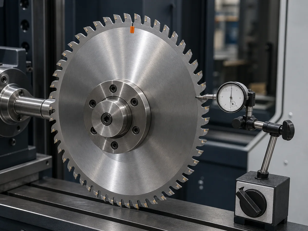
Quick answer: Lock out the machine, clean the
mounting stack, measure arbor radial runout and flange-face axial runout
first, then mount the blade and measure blade-body axial runout near the
rim. Mark the high point, rotate the blade to another angular position
on the arbor, and measure again. If the high point follows the blade,
investigate the blade. If it remains fixed to the machine, investigate
the arbor, flange and mounting surfaces.
What Saw Blade Runout Means
Runout is the total movement shown by an indicator while a component
completes one slow revolution. The reported value is normally
total indicated runout (TIR): the highest reading minus
the lowest reading. Do not report only the positive deviation or confuse
TIR with a plus/minus tolerance.
Runout must always identify the measured surface and direction. “The
blade has 0.10 mm runout” is incomplete unless the report says whether
that value was measured on the blade body, tooth circle, bore, arbor or
flange face.
Axial Runout vs Radial
Runout
| Measurement | Indicator direction | What moves | Typical effect |
|---|---|---|---|
| Blade-body axial runout | Probe parallel to spindle axis | Blade side face moves left/right | Wider kerf, poor finish, vibration, uneven tooth loading |
| Flange-face axial runout | Probe contacts flange face | Flange face wobbles | Blade is forced to run at an angle |
| Arbor radial runout | Probe points toward spindle center | Arbor surface moves up/down | Eccentric rotation and changing chip load |
| Tooth-circle radial runout | Probe follows tooth radius or a controlled reference | Tooth tips vary in radius | Some teeth cut more than others |
Axial blade runout is often called side runout, lateral runout or
wobble. Radial runout is often called eccentricity. They require
different indicator positions and should be recorded separately.
Symptoms That Can Point to
Runout
Runout can contribute to a rough edge, oversize kerf, alternating saw
marks, noise, short edge life, burrs and heat. However, those symptoms
can also come from incorrect RPM, feed, tooth count, coolant, clamping
or dynamic balance.
This is why visual symptoms should trigger measurement—not an
immediate blade replacement.
Tools and Inspection
Conditions
Use a calibrated dial indicator or digital indicator, a rigid
magnetic stand, a clean lint-free cloth, a non-damaging marker and the
machine or blade manufacturer’s inspection procedure. A precision
straight arbor or inspection fixture is useful when the blade must be
checked away from the saw.
| Item | Recommended practice | Avoid |
|---|---|---|
| Indicator | Resolution appropriate to the specified tolerance | Loose, sticky or unverified gauge |
| Stand | Short, rigid arm locked firmly | Long flexible arm that amplifies movement |
| Contact point | Smooth, stable surface away from slots and teeth | Expansion slots, labels, burrs or damaged areas |
| Rotation | Slow manual rotation in one direction | Motor-powered rotation during contact measurement |
| Record | Surface, radius, orientation, min, max and TIR | A runout number without method or location |
Safety: Lock Out Before
Measurement
Disconnect and lock out machine power according to the facility
procedure. Confirm that the spindle cannot start. Wear cut-resistant
gloves when handling the blade, but keep gloves and loose clothing away
from any rotating assembly. Turn the spindle only by the safe manual
method allowed by the machine manufacturer.
Never hold the indicator by hand against a powered blade.
Step 1: Clean and
Inspect the Mounting Stack
Remove chips, dried coolant, resin, corrosion and raised burrs from
the arbor shoulder, inner flange, outer flange, spacers and blade faces
around the bore. A thin contaminant trapped on one side can tilt a blade
even when the plate itself is flat.
Check for nicks, fretting marks, uneven wear, distorted pin holes and
damaged threads. Cleaning is part of the measurement process because an
assembly measured with debris does not describe the machine’s true
condition.
Step 2: Measure
Arbor or Spindle Radial Runout
Remove the blade. Position the indicator so the probe contacts a
clean cylindrical arbor reference surface and points toward the spindle
centerline. Preload the gauge slightly, zero it, and rotate the spindle
slowly through one revolution.
Record minimum, maximum and TIR. Repeat at a second axial location
when the accessible arbor length permits. A changing value along the
arbor can indicate taper, damage or bending rather than simple
eccentricity.
Step 3: Measure
Flange-Face Axial Runout
Place the probe against the cleaned inner flange face near its
working radius, with the probe approximately parallel to the spindle
axis. Rotate slowly and record TIR. Repeat at another radius if the
flange geometry allows.
A flange may look clean and still have face error. Equal, parallel
and adequately supporting flanges help the blade remain stable;
published Freud and Leitz guidance commonly describes flange support
around one-quarter to one-third of blade diameter, but the saw and blade
manufacturer’s specification takes priority.
Step 4: Mount the Blade
Correctly
Confirm the blade bore, pin-hole pattern, rotation direction and
maximum RPM. Seat the blade flat against the inner flange without
forcing it. Install the outer flange and tighten using the specified
sequence and torque.
Do not use the arbor nut to pull a damaged or incorrectly sized bore
into position. Do not add improvised paper, foil or uneven shims to
“correct” runout.
Step 5: Measure
Blade-Body Axial Runout
Place the indicator on a clean continuous band of the blade body near
the outer rim but below the gullets, carbide tips and expansion slots.
Keep the probe perpendicular to the local blade face and use light
preload.
Rotate the blade slowly through one revolution. Mark the angular
location of the maximum reading and record the measurement radius.
Repeat once to confirm repeatability.
Measuring too close to the flange can hide plate movement. Measuring
on slots, laser cuts, printed graphics or damaged areas creates false
peaks.
Step 6:
Check Tooth-Circle Radial Variation Carefully
Tooth-circle measurement requires a method that accounts for tooth
geometry. Alternating-top-bevel, triple-chip and combination blades
intentionally have different tooth shapes, so touching random tooth
faces does not produce a valid radial comparison.
Use the manufacturer’s fixture or compare equivalent reference points
on teeth of the same geometry group. For resharpened blades,
inconsistent tooth height may reflect grinding variation even when the
plate body runs acceptably.
Step
7: Use the Indexing Test to Separate Blade and Machine Error
Mark the blade and flange at the 12 o’clock mounting position.
Measure and mark the blade’s high point. Remove the blade, rotate it
relative to the flange—for example 120 or 180 degrees where the pin-hole
pattern permits—remount it correctly and repeat.
| Result after indexing | Most likely direction | Next check |
|---|---|---|
| High point follows the blade mark | Blade plate, bore or tooth circle | Check blade on certified inspection arbor |
| High point remains at machine position | Arbor, flange, shoulder or machine bearing | Recheck machine without blade |
| Reading changes unpredictably | Dirt, inconsistent torque, damaged contact surface or flexible setup |
Clean, stabilize and repeat |
| Runout improves at one orientation | Combined blade and machine errors partially cancel | Repair the source; do not rely on lucky indexing |
Indexing is diagnostic, not a production correction. A blade that
only meets requirements at one accidental orientation may fail after
normal removal and remounting.
Diagnose the Pattern,
Not Only the Number
| Indicator pattern | Possible cause | Confirmation action |
|---|---|---|
| One smooth rise and fall per revolution | Tilted flange, bent plate or eccentric arbor | Index blade; measure flange and arbor separately |
| Sharp isolated spike | Burr, dent, weld contamination or probe crossing a slot | Inspect the exact marked location |
| Multiple repeating peaks | Tooth-height variation, plate distortion or measurement on features |
Compare equivalent teeth and body surface |
| Reading changes when tightening | Uneven flange, excessive torque, dirt or damaged bore | Clean and repeat with specified torque |
| Acceptable static runout but vibration at speed | Dynamic balance, resonance, bearing or process problem | Continue with dynamic-balance diagnosis |
Blade, Arbor, Flange or
Mounting Dirt?
Treat the rotating stack as a chain. An accurate blade cannot run
accurately on a damaged arbor. A straight arbor cannot compensate for an
uneven flange. Clean flanges cannot make an overheated blade plate flat
again.
The efficient order is: clean → arbor → flange → blade body →
tooth circle → powered cutting test. This prevents repeated
blade changes that leave the true machine fault untouched.
Runout vs Dynamic
Balance vs Plate Tension
Runout is geometric movement measured during slow rotation. Dynamic
imbalance is unequal mass distribution that produces force at operating
speed. Plate tension is the internal stress condition that helps a blade
remain stable under centrifugal force and cutting heat.
A blade can have low static runout but poor balance. It can also show
acceptable balance but lose stability because tension is wrong. Continue
with our saw blade
dynamic balance and vibration guide and saw blade tensioning and
straightening guide when the static geometry does not explain the
cutting symptom.
New, Used
and Resharpened Blades Need Different Checks
For a new blade, preserve packaging evidence and measure the machine
first before filing a supplier claim. For a used blade, inspect heat
discoloration, impact marks, pitch buildup and side contact. For a
resharpened blade, compare tooth height, side clearance, hook angle and
plate condition as well as body runout.
Leitz notes that inaccurate sharpening can contribute to lateral
runout, and a severely overheated or discolored plate may no longer be a
safe repair candidate. Use the saw blade resharpening guide
to decide whether inspection, correction or replacement is
appropriate.
Large-Diameter
and Thin-Kerf Blades Are More Sensitive
The same angular error creates greater side displacement farther from
the spindle center. Large-diameter blades therefore need rigid machines,
suitable flange support and measurement at a documented radius.
Thin-kerf plates can also respond more strongly to clamping error, heat
and side load.
Do not transfer a tolerance from a small woodworking blade to a large
industrial cold saw. Ask the supplier for the specification applicable
to the exact diameter, plate thickness, tooth design, machine and
measuring method.
What Runout Limit
Should a Buyer Specify?
There is no responsible universal value for every saw blade. The
acceptance limit should come from the blade drawing, machine manual,
applicable standard and the required cut quality. A useful purchase
specification defines both the number and the test method.
| Specification field | Example of what to define |
|---|---|
| Component | Blade body, bore, tooth circle, arbor or flange |
| Direction | Axial or radial |
| Measurement radius | Exact radius or distance below tooth root |
| Mounting fixture | Inspection arbor/flange dimensions and fit |
| Clamping | Torque or fixture procedure |
| Reporting | Maximum, minimum, TIR, gauge resolution and temperature |
The saw blade bore size
guide explains why bore fit, pin holes and flange interfaces must be
specified together.
Inspection Report Template
Record blade SKU and serial/batch, diameter, bore, plate thickness,
tooth count, machine ID, arbor and flange dimensions, indicator model
and resolution, measurement radius, mounting orientation, tightening
method, min/max/TIR and photos of the setup.
For supplier communication, include readings before and after
indexing. A single photograph of an indicator without its contact point,
zero reference and blade orientation is not enough to diagnose
responsibility.
Common Measurement Mistakes
- Measuring the mounted blade before checking the bare arbor and
flange. - Letting the probe cross an expansion slot or laser cut.
- Using a flexible indicator arm.
- Reporting one dial reading instead of maximum-minus-minimum
TIR. - Measuring unlike tooth geometries as if they were identical.
- Rotating the blade under motor power.
- Tightening inconsistently between tests.
- Treating dynamic vibration as proof of static runout.
Troubleshooting
Workflow for Poor Cutting
If a new blade cuts poorly, verify mounting cleanliness, arbor/flange
condition and runout before changing feed or sending the blade back. If
the geometry passes, continue to tooth count, RPM, feed, coolant,
workpiece support and clamping.
Our new saw
blade cuts poorly diagnostic guide connects these checks into one
machine-versus-blade workflow.
Questions Buyers
Should Send With an RFQ
- What axial and radial runout is guaranteed, and at what measurement
radius? - Is the value measured on the body or tooth circle?
- What inspection arbor, flange diameter and clamping method are
used? - Is each blade checked after brazing, grinding and tensioning?
- Can the supplier provide a runout and balance report for
large-diameter blades? - What is the recommended machine arbor fit and flange support?
- What happens if field readings differ from the factory report?
Frequently Asked Questions
Can I
measure saw blade runout with the blade installed?
Yes, but that reading describes the complete blade-machine mounting
stack. Measure the bare arbor and flange first if the goal is to
identify whether the blade itself is responsible.
Where should
the dial indicator touch the blade?
For axial blade-body runout, use a clean continuous band near the
outer rim but below the gullets and carbide teeth. Document the exact
radius and avoid slots, labels, burrs and damaged areas.
Does a
wobbling blade always mean the plate is bent?
No. Dirt, flange-face error, arbor runout, incorrect bore fit, uneven
tightening and bearing problems can all make a straight blade appear to
wobble.
Can I
correct runout by rotating the blade on the arbor?
Rotating the blade is useful for diagnosis. It should not be treated
as a permanent correction because combined errors may only cancel at one
accidental orientation.
Is runout the same as blade
balance?
No. Runout is geometric movement during slow rotation; imbalance
produces centrifugal force at speed. Both can affect finish and blade
life, but they require different tests.
Heat, chip adhesion and recutting can distort both cutting performance and inspection results. Use our saw blade coolant and lubrication guide to compare flood coolant, MQL, dry cutting and nozzle setup.
Related guide: Why Cold Saw Blade Teeth Chip: Buyer Troubleshooting Guide adds a practical buyer checklist for cold saw blade teeth chip.
Final Recommendation
Do not approve or reject a circular saw blade from one unexplained
dial reading. Clean the assembly, isolate arbor and flange error,
measure axial and radial movement at documented locations, and use an
indexing test to see whether the high point follows the blade or stays
with the machine. A repeatable method protects both cut quality and
supplier accountability.